Apart from creating a Test Configuration, with all the details of the equipment installed, to set up your routes - there is an option to set up Pre-Routes before any Equipment is added.
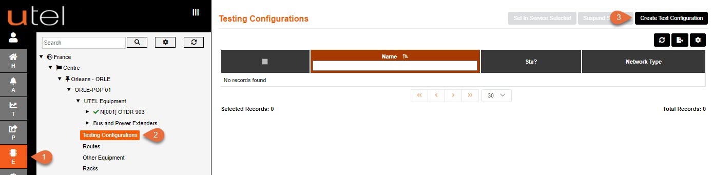
Select Element Manager from the Menu bar.
In the Tree, select the relevant POP Site and then Test Configurations.
Click the Create Test Configuration button.
Below is the screen that is presented with the UTEL Equipment created.
All the fields are filled in with the default settings for quick creation:
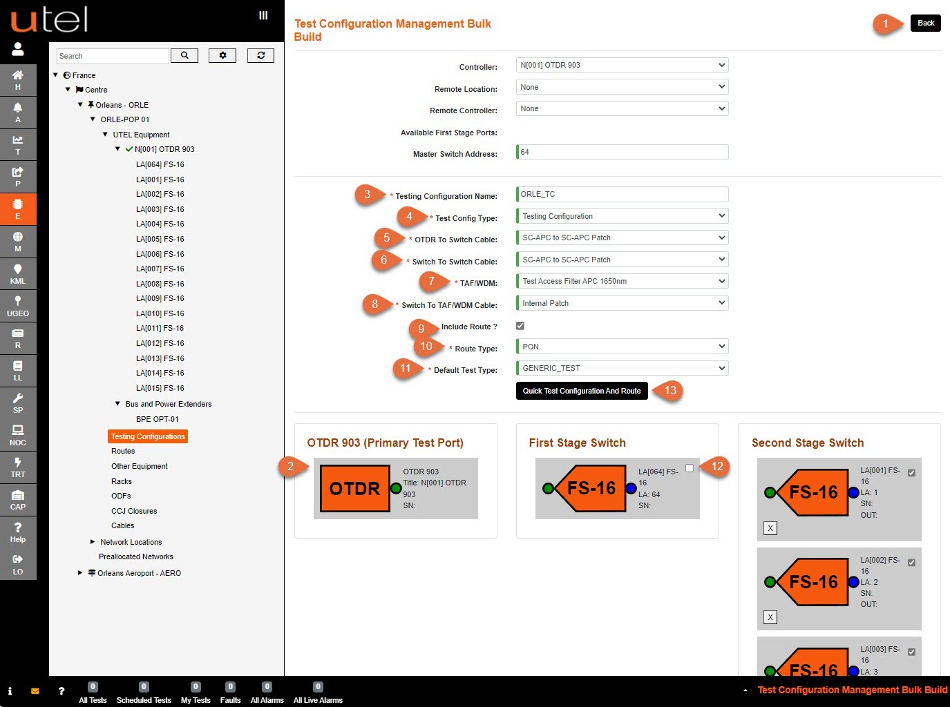
1.The screen will now display the UTEL Equipment you have built in the Network so far.
If there are elements missing from this screen or incorrect Logical Addresses (LAs) for your Switches, then they may have been added incorrectly.
Select Back and edit these if necessary.
2.The correct Controller (OTDR 903) should display automatically at the top of the screen.
If you wish to edit, select the one you require from the drop-down menu or the location and name of the remote controller if it is a ROSC.
3.Enter a Test Configuration name as you would like it to display in the Tree.
Please refer to the Naming Convention part of this document for guidance.
If so, the name will appear similar to the image above.
4.Test Configuration Type should automatically be the correct one for the location created.
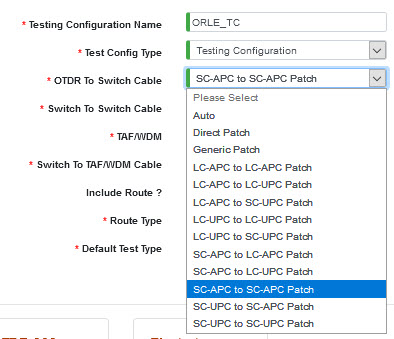
5.Select the Patch Cable used for the OTDR To Switch Cable.
6.Select the Patch Cable used for the Switch To Switch Cable, which has the same options;
7.Select Test Configuration TAF required;
None, APC 1650nm or UPC 1650nm.
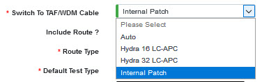
8.Select Switch To TAF/WDM Cable from the drop-down menu;
9.Include Route? to allow for routes to be available from the tree; if so then proceed with 10 - 12.
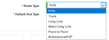
10.Select Route Type from the drop-down menu;
11.Select Default Test Type from the drop-down menu.
12.Select the Master Switch when required for network routing, via the tick box.
Any Switches not to be included in setting up routes can be deselected.
13.Once all the above is correct, select the Quick Test Configuration and Route button.
Below is the screen that is presented without the UTEL Equipment created.
This allows pre-routes for the network to be connect up before the switch ports are available:
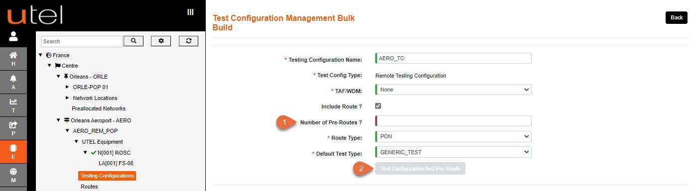
1. Enter the number of Pre-Routes required.
2. Once all details are configured as required, select the Test Configuration and Pre-Route button when it becomes available.
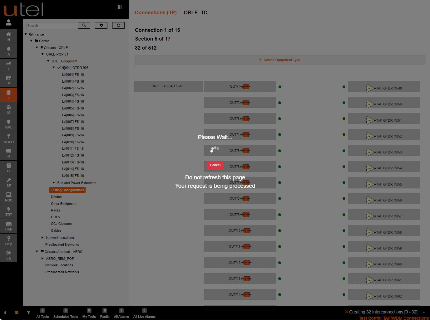
The system will make connections between the OTDR, the Master Switch and the cascaded Switches.
The Routes will be automatically be created.
This may take up to a minute, depending on the number of connections to be made.
When the Test Configuration is complete you will be presented with the Details.
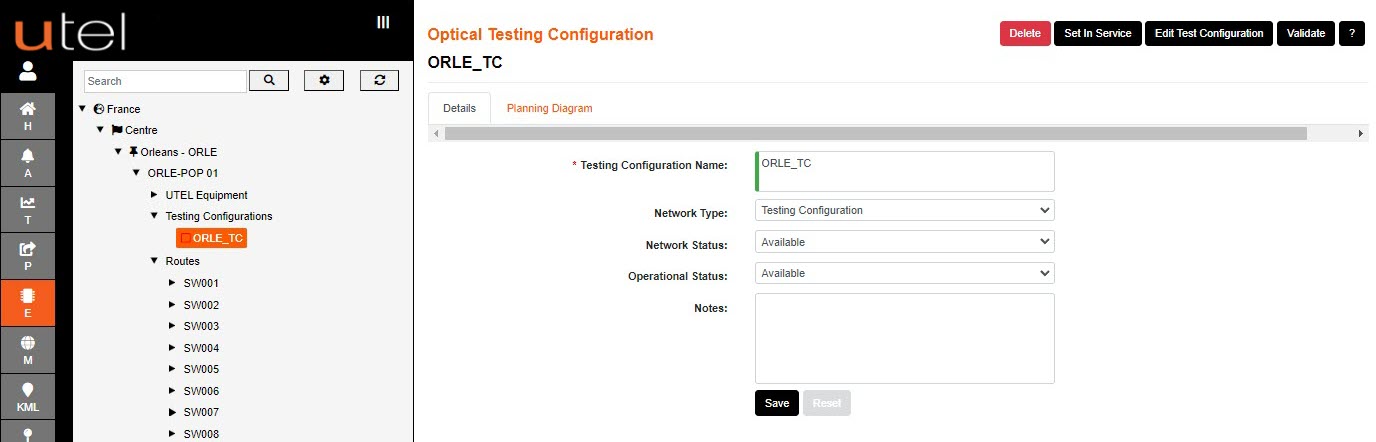
The connections will be displayed in a Planning Diagram.
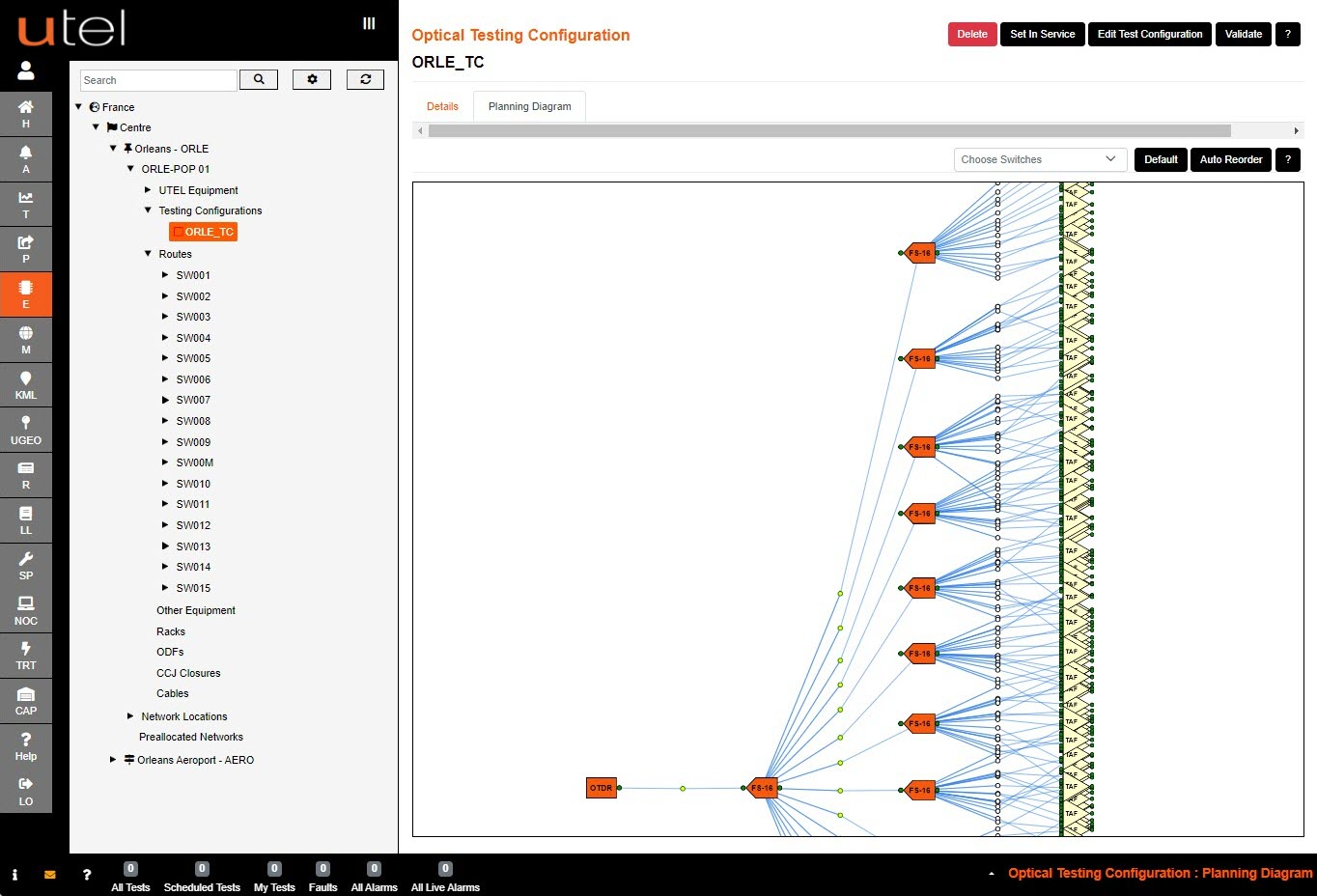
You are able to zoom in and out of the diagram using the scroll on your mouse to view it closer.
The Switch filter will allow a simplified view, especially as more of the network is added to the routes.
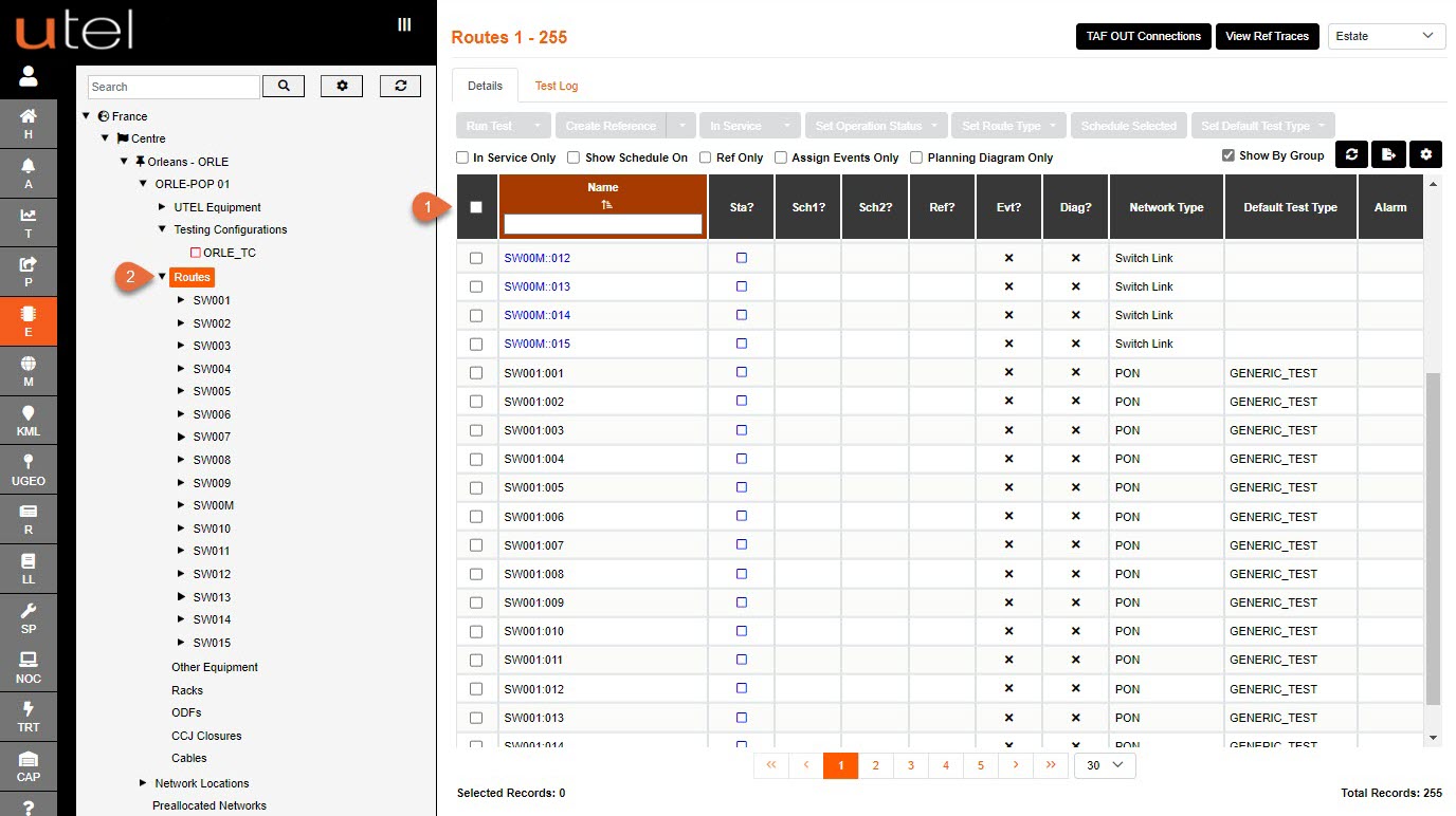
FastLight will display the Routes in a table view (1).
They will also appear grouped together in the Tree (2).
To view all the Routes in this table view, select Routes from the Tree.
To view an individual route, select its name from the Tree view.