As soon as you have created a cable from the POP then you can complete the set up of the route within the POP.
Note: Cables can be created without the Map, in Network Locations, if by any chance Map/Project is not enabled.
Cables can be easily created via the GIS Mapping function which will be covered in GIS Mapping Data Build Guide.
Click on an item on the map from which you wish to start creating your cable from.
Click on the Create Cable button.

Select End Item, option will be presented if an existing joint closure exists.

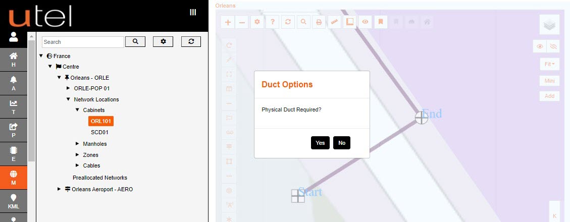
Some cables can be created without the need of a duct, but due to the fact that the cable is not known at this point the option is presented.
Select Yes to use the Physical Duct, and No if not.
In this example we are using a duct.
Click on the Green Target on the correct path, as there might be multiple paths to the point seelcted.
If there is a Microduct or Multiduct within a Singleduct path, then all items will be presented to select.
For this example we are using the Multiduct.
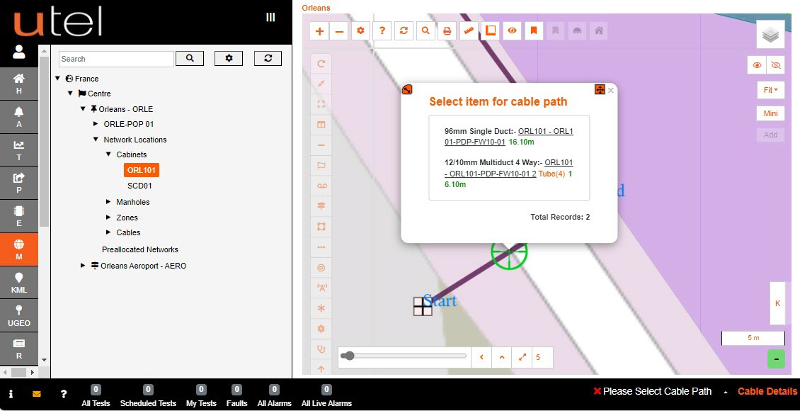
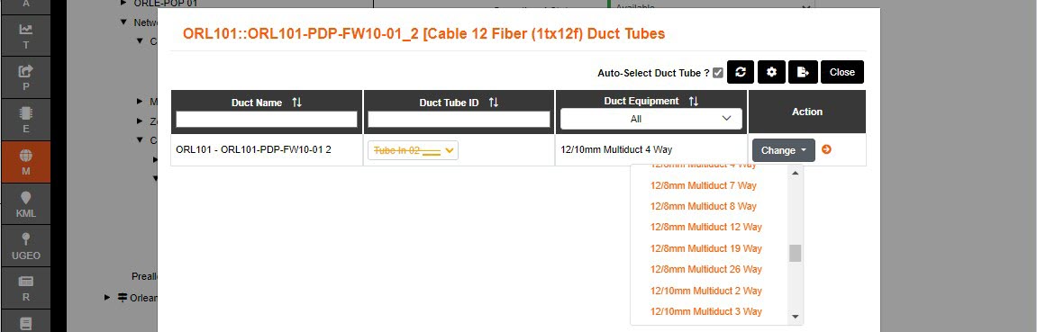
The option to choose the tube that the cable is to lay in is then presented.
Select the Tube required to use, any crossed through means that the tube is already used.
The tube selected will be displayed on the highlighted section chosen as the cable path.
With a cable along multiple ducts, the Advanced Settings 'Auto Select Next Tube' will select the ripple down the same tube selected in the first instance;
On allows each click of the path to use the same tube, without presenting the tube pop up after the first selection.
Off allows you to choose the tube you need to use; if they are not the same throughout each section of duct.

Having chosen the tubes, the user is prompted to Edit to navigate to the cable form, Edit Tube, or Cancel.
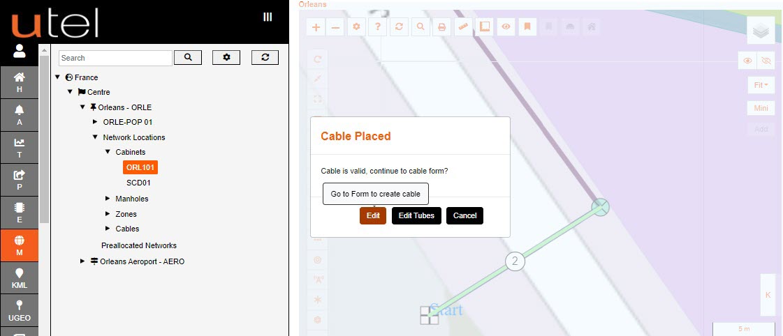
Selecting Edit Tube will allow the user to edit any tubes selected along the path.
'Cancel' to exit cable creation all together.
When creating cable via the button, rather than from the toolbar, the user needs to select the cable type in the form.
If you have the 'Default Name' enabled in your user account a suggested Cable Name will be filled in for you, once you have filled in the desired options.
Any field with a * before the name means it is a compulsory field and you must input something here e.g. *Cable Name.
When you enter text here, this will then turn the red marker line at the start of the field to green.
Only when all the lines are green will the Add button appear orange allowing you to press and save your entry.
Create a Cable Name according to your Naming Convention.
Select a Cable Type from the drop-down menu.

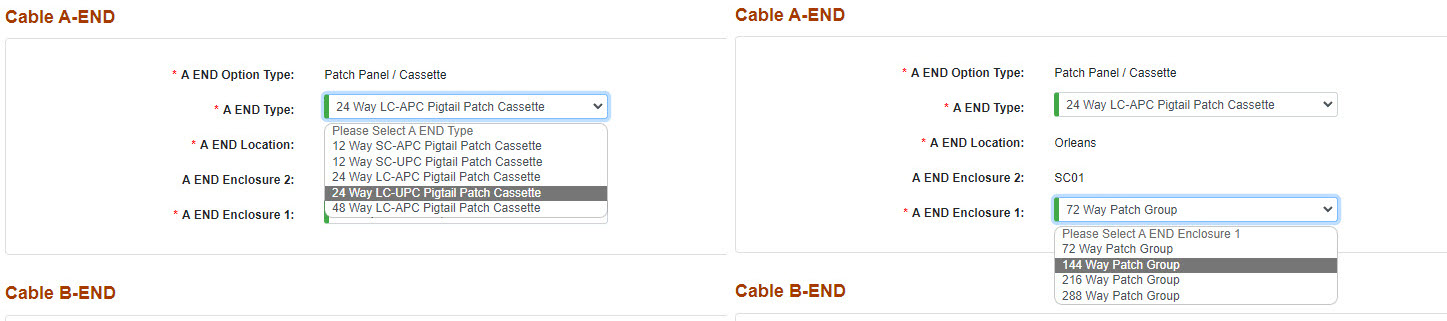
The ‘A END’ of the cable is the start of the cable, building from the Central Office out towards the Customer.
The B END is the end of the cable.
The details will automatically be filled in from the point you chose to create the cable from.
If the cable starts or ends at a Cabinet or POP, then the type defaults to Patch Panel/Cassette, and can be easily modified to the following options in the drop down.
The default is to a New Joint Closure if Manhole/Pole was selected, or Existing if you chose to use an existing Joint Closure in the Manhole/Pole.

Choose the appropriate Network Status and Operational Status of the Cable using the drop-down menus provided.
The default being Available if created directly from the Map function.
If created from Projects; the status will be Planning and Unavailable.
There are two more optional fields to complete: Predicted Length and Notes.
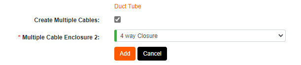
There is an option to create multiple cables if intermediate Manholes/Poles are on the duct route, that the cable is getting laid into.
Selecting this option automatically creates Joint Closures, including their splices, and individual cables between these points.
Select Duct Tube to see list of tubes selected - this helps if the cable is laying in multiple ducts.

To save the cable, select the Add button. The Add and Create Next Section button will present you with another form to enter details for the next section of cable.
FastLight will build this cable into your Network which may take a couple of seconds.
The Cable will show in the Tree, along with the Joint Closures created in the relevant Manholes.
Cables can edit their tubes at any time by navigating to Details (either via Map, Tree or Element), and select Duct Tube 'Change'.
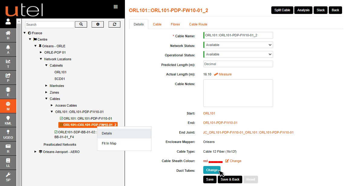
Duct Tube drop down shows the options to choose another tube.
The ducts that have been auto selected will be highlighted, with the options not including a duct that has already been selected (and occupied).
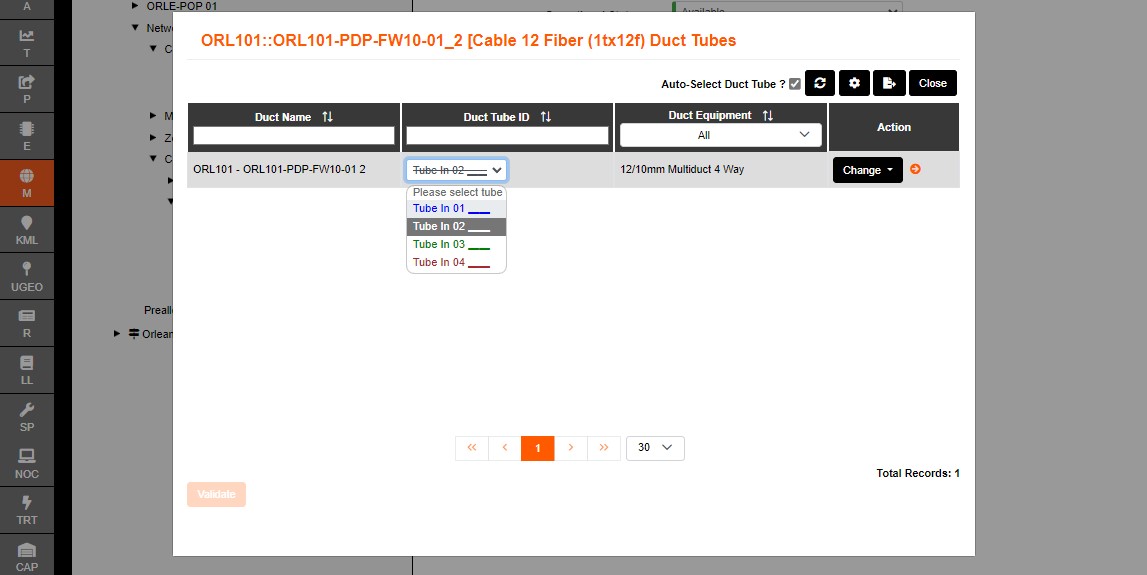
All the details displayed in the summary can be directly edited on this screen.
The tubes can be modified at any point. Select from the drop down, and then 'Validate'.
If the Duct is not big enough, then select 'Change' to select a bigger option.
Should you make any changes, the Save button will highlight orange to remind you to save.
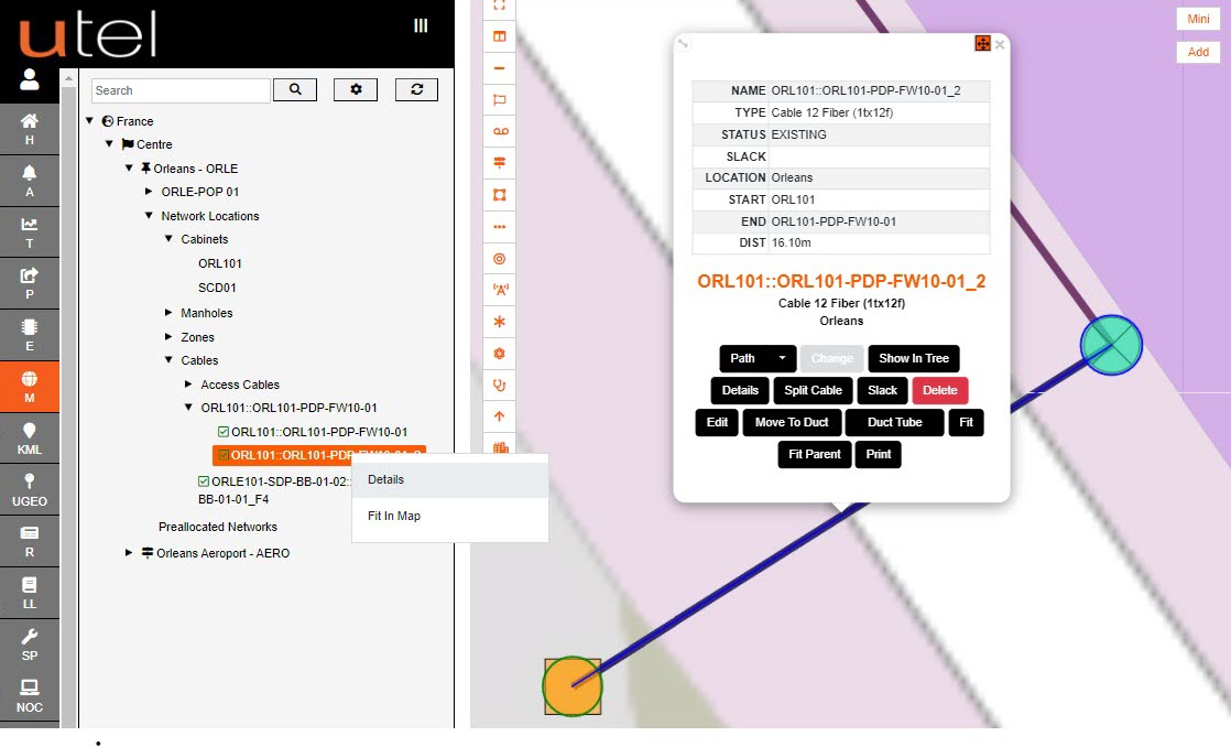
A cables information can be viewed at any time. Clicking on a cable presents a pop up.
Hovering over the orange name will present a table (similar to Google map).
If any help is required to understand the rules around creating with different types of cables - the Help button on the top right of the form when creating a cable will present a helpful pop up.
There is also help for all items on the map; select the ? or press h on your keyboard.
