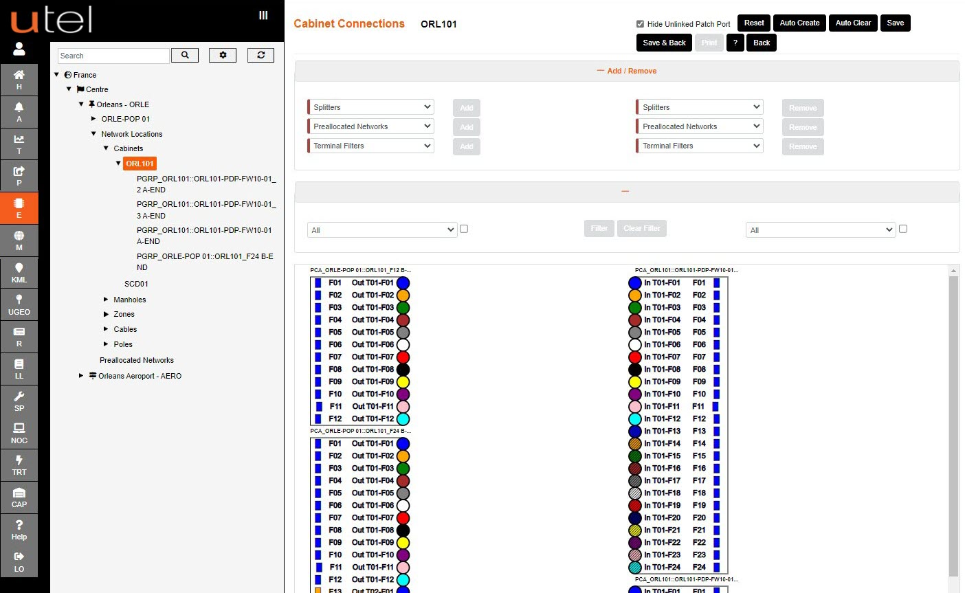
Within a Cabinet, Manhole Joint Closure/CBT, Pole Joint Closure/CBT, Distribution Point, Network Termination or a POP where cables are connected, you can draw in the connections between the cable ends to show how it’s been spliced or connected together.
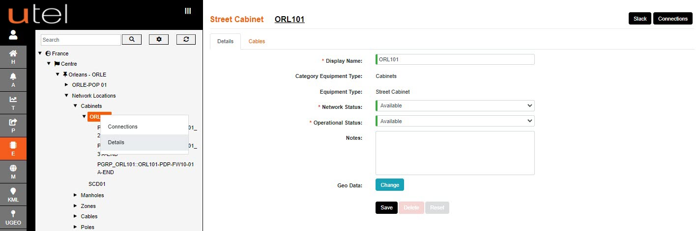
From the tree navigate to the name of the Network Location you wish to modify/view.
Click the Connections button in the top right-hand corner of the screen.
There is also an option to hyperlink to the Connections screen (and Details) upon right clicking on the name in the tree.
Click on the left-hand cable and drag across to the right-hand side to create a connecting cable.
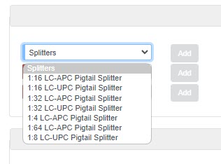
You can add Splitters by selecting the size of the Splitter from the minimized menu, naming it and clicking on Add Splitter.
Then drag the Splitter to the correct place in the diagram, and drag and drop to draw in the connections.
When you have finished drawing, select Save.

There is the option on every Connection Screen to double click on the cables A-END or B-END to go to next or previous Connection Screen.